Beyond the Plume: A Water Monitoring Routine for UK Cooling Towers and Evaporative Systems
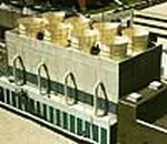
Photo: The original uploader was Mbeychok at English Wikipedia., CC BY-SA 3.0, via Wikimedia Commons
Cooling towers and evaporative condensers are among the most water-intensive assets on many UK industrial sites, yet their losses are often poorly understood. Evaporation is expected. Drift is accepted as a design allowance. Blowdown is necessary to control dissolved solids. The problem is that these normal losses can mask abnormal ones: a solenoid valve stuck open, a basin overflowing, a mains make-up line leaking underground, or a pump seal passing water into the sump. None of these produces the dramatic burst-pipe event that a facilities team would notice immediately. Instead, the site receives a bill spike weeks later, or a water-quality excursion that triggers a compliance question.
A monitoring routine for cooling water should therefore be built around mass balance and routine verification, not around a single leak sensor. The aim is to know what the tower should be losing, measure what it is actually losing, and investigate the difference before it becomes a commercial or compliance problem.
Why cooling water losses stay quiet
Evaporative cooling consumes water by design. The volume lost to evaporation depends on heat load, ambient conditions and tower performance. Drift is a smaller but persistent loss, and blowdown is controlled by cycles of concentration. When these legitimate losses are combined, the makeup water meter may run for long periods without attracting attention. A slow leak on the make-up line, or a blowdown valve that never fully closes, can sit within the noise of normal operation.
Basin overflow is another quiet failure. A float valve may be misadjusted, a level probe may drift, or a control valve may fail open. The overflow may discharge to a drain in a plant area where nobody looks. In winter, the same fault can create ice risk; in summer, it can waste thousands of litres before the next site walk.
Water quality adds a second layer. A cooling tower is a potential Legionella risk if it generates aerosol and is not properly managed. UK duty holders are expected to follow the requirements of L8 and HSG274, including risk assessment, written schemes, temperature and biocide control, and routine sampling. Monitoring data from the water side can support that regime, but it does not replace laboratory analysis or competent person oversight.
Start with a water balance, not a sensor list
The first step is to establish what normal looks like. Install a dedicated submeter on the makeup water line to each cooling system, with a pulse or digital output that can be trended. Where possible, meter blowdown separately. Estimate evaporation from heat load or from tower performance data, and calculate the expected makeup volume. The gap between expected and measured makeup is the first diagnostic tool.
A simple monthly mass balance is more useful than an elaborate dashboard that nobody reviews. If the measured makeup exceeds the calculated evaporation plus blowdown by a consistent margin, investigate. If the gap appears suddenly, treat it as a potential leak or valve failure. If it grows gradually, look for drift, changing cycles of concentration or a slowly passing valve.
The monitoring layer
A practical monitoring layer for a UK industrial cooling site usually includes the following elements.
- A dedicated makeup water meter with a clear trend and a night-flow or no-load flow alarm.
- Basin level indication with high and low alarms, plus valve position feedback where a motorised make-up valve is fitted.
- Conductivity measurement on the circulating water to control blowdown and cycles of concentration.
- A blowdown meter or valve-status signal to confirm that blowdown stops when it should.
- Leak detection in the plant room and around the basin, particularly where pipework is concealed.
- Pump current or vibration monitoring to catch dry running, cavitation or mechanical wear.
- Water-quality checks for temperature, biocide residual, pH, conductivity and turbidity, alongside the scheduled Legionella sampling programme.
These signals do not all need to be connected to a single platform. What matters is that they are reviewed together. A rising makeup volume, a falling basin level and a normal blowdown signal point in one direction. A stable makeup volume with a rising conductivity and a stuck blowdown valve point in another.
Alerts that prompt action
Alarm design should reflect the operational reality of the site. Continuous makeup flow during a production shutdown is a strong indicator of a passing valve or a leak. Basin level instability may indicate a faulty level probe or a sticking valve. A blowdown valve that remains open outside its scheduled window is wasting water and may be affecting chemistry. A conductivity reading that drifts away from target suggests that the blowdown control is not responding.
Alarm fatigue is a genuine risk. A tower with a variable load will have variable makeup demand, so a simple high-flow alarm may nuisance-trip. Better rules use time-of-day, production status and rate of change. For example, a makeup flow that continues for more than a set period when the plant is idle is more meaningful than a raw high-flow threshold.
A practical maintenance cadence
The monitoring routine should be written into the site's maintenance schedule and assigned to named roles.
Daily checks should include a visual inspection of the tower and basin, review of any active alarms, and a comparison of makeup volume against the previous day's baseline. A quick look at basin level and blowdown status is also worthwhile.
Weekly tasks should cover conductivity and biocide residual checks, filter cleaning or inspection, and a review of pump current. This is also the point to confirm that the blowdown valve is opening and closing on command rather than merely being assumed to do so.
Monthly activities should include the mass balance review, a functional test of level alarms and leak sensors, and a check of make-up valve operation. If the site has multiple towers, compare their water use per unit of cooling load; unexplained divergence is a useful early warning.
Quarterly work should include a review of the Legionella risk assessment and written scheme, inspection of drift eliminators and fill, verification of backflow protection on the makeup line, and calibration checks on conductivity and level instruments. Annual tasks should include a full review of the water treatment programme, a review of sampling results and a check that the monitoring system still reflects the installed plant.
Documentation and compliance
Monitoring records are valuable evidence. They show that the site has a routine, that alarms are reviewed and that corrective actions are taken. In a Legionella incident or an insurance claim, that evidence matters. The records should sit alongside the water treatment log, the sampling results and the maintenance schedule, not in a separate folder that nobody reconciles.
Cooling towers will always lose water. The objective is not to eliminate evaporation or blowdown, but to ensure that the losses the site pays for are the losses it intends. A disciplined routine of submetering, mass balance, targeted alarms and water-quality verification will catch the quiet failures while they are still cheap to fix.